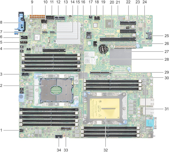
Jumpers and Connectors
This topic provides specific information about the jumpers and switches and describes the connectors on the board in the system. Jumpers on the system board help to disable the system and setup passwords. You must know the connectors on the system board to install components and cables correctly.

|
Item |
Connector |
Description |
|---|---|---|
|
1. |
FAN6 |
Cooling fan 6 connector |
|
2. |
CPU1 |
Processor socket 1 |
|
3. |
CPU1_PWR_CONN(P2) |
CPU1 power connector |
|
4. |
J_INTRU |
Intrusion switch connector |
|
5. |
J_BP_SIG1 |
Backplane signal connector 1 |
|
6. |
LFT_CP_CONN |
Left control panel connector |
|
7. |
J_SATA_B1 |
Internal SATA B connector |
|
8. |
RGT_CP_CONN |
Right panel connector |
|
9. |
SYS_PWR_CONN(P1) |
System power connector |
|
10. |
J_PIB_SIG1 |
Power interposer board signal connector 1 |
|
11. |
J_PIB_SIG2 |
Power interposer board signal connector 2 |
|
12. |
J_ACE |
Internal Dual SD Module |
|
13. |
J_CP_USB2 |
Front USB connector |
|
14. |
J_SATA_A1 |
Internal SATA A connector |
|
15. |
J_SATA_C1 |
Internal SATA C connector |
|
16. |
PCIE_G3_X8(CPU1) |
Internal PERC controller connector |
|
17. |
J_REAR_BP_PWR1 |
Rear backplane power connector |
|
18. |
J_FRONT_VIDEO |
VGA connector |
|
19. |
INT_USB_3.0 |
USB connector |
|
20. |
NVRAM_CLR |
Clear NVRAM |
|
21. |
PWRD_EN |
Reset BIOS password |
|
22. |
SLOT5 |
PCIe slot 5 |
|
23. |
SLOT4 |
PCIe slot 4 |
|
24. |
SLOT3 |
PCIe slot 3 |
|
25. |
J_TPM_MODULE |
TPM module connector |
|
26. |
J_BP_SIG0 |
Backplane signal connector |
|
27. |
J_MEZZ_A1 |
LOM riser card connector |
|
28. |
BATTERY |
Battery connector |
|
29. |
PCIE_G3_X16(CPU1) |
Riser 1 connector |
|
30. |
A6, A5, A10, A4, A9, A7, A1, A8, A2, A3 |
Memory module sockets |
|
31. |
B3, B2, B1, B4, B5, B6 |
Memory module sockets |
|
32. |
CPU2 |
Processor socket 2 |
|
33. |
PCIE_A0 |
NVMe connector |
|
34. |
CPU2_PWR_CONN(P3) |
CPU2 power connector |
System board jumper settings
For information on resetting the password jumper to disable a password, see the Disabling a forgotten password section.
Disabling forgotten password
The software security features of the system include a system password and a setup password. The password jumper enables or disables password features and clears any password(s) currently in use.
CAUTION: Many repairs may only be done by a certified service technician. You should only perform troubleshooting and simple repairs as authorized in your product documentation, or as directed by the online or telephone service and support team. Damage due to servicing that is not authorized by Dell is not covered by your warranty. Read and follow the safety instructions that are shipped with your product.
Follow the below steps to disable forgotten password.
1. Power off the system, including any attached peripherals, and disconnect the system from the electrical outlet.
2. Remove the system cover.
3. Move the jumper on the system board jumper from pins 2 and 4 to pins 4 and 6.
4. Install the system cover.
The existing passwords are not disabled (erased) until the system boots with the jumper on pins 4 and 6. However, before you assign a new system and/or setup password, you must move the jumper back to pins 2 and
Note: If you assign a new system and/or setup password with the jumper on pins 4 and 6, the system disables the new password(s) the next time it boots.
5. Reconnect the system to its electrical outlet and power on the system, including any attached peripherals.
6. Power off the system, including any attached peripherals, and disconnect the system from the electrical outlet.
7. Remove the system cover.
8. Move the jumper on the system board jumper from pins 4 and 6 to pins 2 and 4.
9. Install the system cover.
10. Reconnect the system to its electrical outlet and power on the system, including any attached peripherals.
11. Assign a new system and/or setup password.


